Ernest Worthman of Semiconductor Engineering recently noted that future ultra-low-power (ULP) IoT devices require a new paradigm for handling cryptography. “To optimize the power in
VirtuOptic™ Reflectors
VirtuOptic™ reflectors deliver a highly efficient, collimated light pattern that can be evenly distributed over wide areas, making it ideal for high brightness architectural, entertainment and commercial lighting applications. When combined with Rambus’ proprietary optical modeling and design techniques, the shape and size of the VirtuOptic reflectors can be optimized to achieve a highly-controlled, directed light output at the desired ray angle for minimal glare.
- Greater than 90% optical efficiency
- Reduced glare with a highly-controlled, collimated light output
- Even light distribution over wide areas
What is VirtuOptic Reflector Technology?
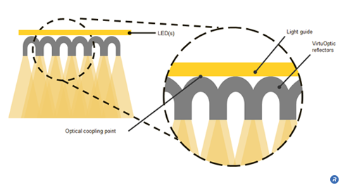
VirtuOptic™ Reflectors take advantage of the optical property of total internal reflection (TIR), which is an extremely efficient means of transporting light. Light is injected into the end of a light guide using Rambus’ TruEdge™ LED coupling technology. It is transmitted down the length of the light guide through TIR with minimal loss, producing a uniform emission of light from the reflective optical elements.
VirtuOptic™ Reflectors are created by bonding an array of high precision reflectors to an optical light guide, using a material with a matching refractive index. Light is extracted from the light guide at the optical coupling points at the center of each VirtuOptic™ Reflector in a near zero-loss transition, creating a uniform array of virtual light sources.
Who Benefits?
Light fixture designers can take advantage of the high-efficiency and unique aesthetic of the virtual light sources created by VirtuOptic™ Reflectors to create cost-effective fixtures with customizable light outputs. The even light distribution produced enables commercial lighting specifiers to save costs and reduce the total number of fixtures required to deliver the desired amount of light to a given surface.
Very Low-Swing Differential Signaling
Today’s mobile device demand high bandwidth for HD video capture and streaming, and media-rich web browsing as well as extended battery life. Very Low-Swing Differential Signaling (VLSD) is a bi-directional, ground-referenced, differential signaling technology which offers a high-performance, low-power, and cost-effective solution for applications requiring extraordinary bandwidth and superior power efficiency.
- Enables high data rates at very low IO power consumption
- Improves signal integrity
What is Very Low-Swing Differential Signaling Technology?
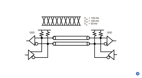
VLSD signals are point-to-point and use an ultra-low 100mV signal swing (50 to 150mV) and 100mV common-mode voltage, which results in a 200mV peak-to-peak differential signal swing. This swing is less than 1/10th the signaling swing of commodity memory interfaces. VLSD enables high data rates with very low IO power consumption.
Who Benefits?
VLSD enables system designers to achieve high-speed operation through the robust signaling characteristics inherent to differential signaling, while minimizing IO power consumption through the use of a ground-referenced low-voltage-swing signaling system. This combination of high-bandwidth and low-power operation improves mobile device performance and battery life for consumers.
TruEdge™ LED Coupling
The growing popularity of LEDs in general lighting applications has introduced great opportunities for a new generations of energy-efficient lighting, but LEDs are not without their difficulties. Designers are challenged with how to transform single, or multiple point sources of light into an aesthetically-pleasing, uniform distribution of light. The use of edge-lit architectures—where LEDs are placed along one or more edges of a light guide—is a highly-efficient means of directing and distributing light. A key component to those architectures, TruEdge™ LED coupling technology optimizes the interface between the LED light source and the light guide to maximize the amount of light injected into the light guide. By combining Rambus’ proprietary optical modeling and design techniques, TruEdge technology can achieve 93 to 96% LED-to-light guide coupling efficiency.
- Optimizes LED-to-light guide interface to maximize coupling efficiency
- Reduces fixture cost with fewer LEDs
- Enables thinner form factors
What is TruEdge™ LED Coupling Technology?
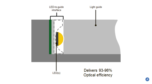
TruEdge™ LED Coupling coupling enables highly-efficient, edge-lit general lighting fixtures that utilize the fewest number of LEDs for a desired light output level. Edge-lit systems can be implemented in a myriad of form factors while producing aesthetically pleasing, diffuse light with minimal glare. This is achieved by optimizing the interface between the LED and light guide through the use of reflectors, couplings lenses and tight LED-to-light guide integration. The combination of these techniques maximizes the efficiency of coupling interface and, in turn, the amount of light delivered from the fixture.
Who Benefits?
When implemented in an edge-lit architecture, TruEdge™ LED Coupling coupling delivers tremendous flexibility of form factor and freedom of design without sacrificing efficiency or control. This will enable designers to create a new age of beautiful and functional lighting. End users will also benefit from the energy-efficient and cost-effective fixtures that are made possible with TruEdge technology.
SolidCore™ Reflectors
Fixtures that use traditional free-space reflectors — those that allow light to travel through air — can be cumbersome and inefficient when producing high-intensity beams of light. As an alternative to free-space reflectors, SolidCore™ reflectors are compact optics that produce high-brightness, collimated beams ideal for high-powered spotlights. SolidCore™ Reflectors enable smaller, thinner and lighter-weight fixtures that can be white or multi-colored by combining reflectors using red, green and blue LEDs.
- High-efficiency, molded reflectors
- Up to 75% reduction in reflector size for equivalent beam angle
- Produces tightly controlled, high-intensity beams ideal for spotlights
- Adjustable light emission according to the radius of the optic
What are SolidCore™ Reflectors?
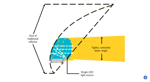
SolidCore™ Reflectors take advantage of the higher refractive index of plastic versus free space to produce a tighter angle of reflection. They are made of molded plastic, and unlike free space reflectors produce less variation in magnification and are far more compact. Each SolidCore reflector uses a single, high power LED. Light is directed to the reflective surface using a customized light pipe. The angle of the high-intensity, concentrated beam emitted by the SolidCore reflectors is determined by the radius of the optic. For example, beam output angles as tight as 3 degrees can be achieved with a 4″ radius optic.
Who Benefits?
With SolidCore reflectors, lighting designers are able to effects with much greater control, precision and intensity than ever before while maintaining power efficiency. The ability to control the beam angle and achieve color mixing delivers a richer and safer experience to consumers in multiple applications including entertainment, architecture, and outdoor lighting.
On Die Termination Calibration
As the performance requirements of digital systems continue to increase, there are increasing requirements to deliver signal integrity that enables reliable operation at higher signaling rates. Signal line terminations are useful elements in the management of signal integrity, and can be use external to the memory device or within the device itself. Incorporating a resistive termination within the DRAM device, which is often referred to as On Die Termination (ODT), improves the signaling environment by reducing the electrical discontinuities introduced with off-die termination. However, variations across process, voltage and temperature (PVT) can cause instability in the resistive characteristics of the ODT elements. Rambus ODT Calibration determines an optimal termination impedance to reduce signal reflections and compensate for variations across PVT.
- Calibrates ODT termination impedance
- Reduces signal reflections
- Compensates for variations across PVT and operating conditions
What is On Die Termination Calibration Technology?
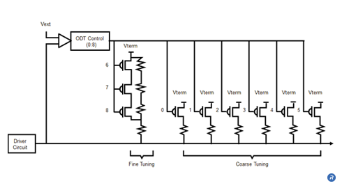
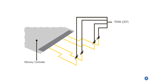
Conventional DRAM memory module architectures typically include line termination resistors on the motherboard. Although the termination resistors on the motherboard reduce some reflections on the signal lines, they are unable to prevent reflections resulting from the stub lines that connect to the DRAMs on the module. A signal propagating from the memory controller to the DRAM encounters an impedance discontinuity at the stub leading to the DRAM on the module. The signal that propagates along the stub to the DRAM will be reflected back onto the signal line, thereby introducing unwanted noise into the signal. The introduced noise and the consequential signal degradations that are not addressed by such off-die termination become more pronounced with higher data rates and longer stub lengths. Larger, multi-drop systems containing multiple DRAM modules introduce even more reflections and consequently add more reflective noise, thereby resulting in further signal degradation.
By placing the termination resistance on the die itself rather than the motherboard, the reflections resulting from discontinuities in the line are significantly reduced, thus producing a cleaner signal and enabling faster data rates.
ODT calibration is a technique that involves calibrating the termination impedance in order to optimize the reduction of signal reflections. ODT calibration allows an optimal termination value to be established that compensates for variations in process and operating conditions.
A calibrated ODT value significantly reduces unwanted signal reflections while only minimally attenuating the magnitude of the signal swing due to the added resistive loading. The resulting cleaner data signal allows for higher data rates.
ODT calibration is achieved by establishing an ODT impedance that is proportional to an external precision resistor. The same external resistor can also be used for Output Driver Calibration.
The ODT calibration controller, compares the voltage drop across the ODT resistor network with a voltage drop across an external resistor represented. The controller modifies the resistor network with coarse tuning and fine tuning to achieve an impedance value that closely approximates the external, reference resistance.
Who Benefits?
ODT calibration delivers benefits at the device, subsystem and system level. By implementing ODT calibration, devices are able to achieve enhanced signal performance and higher data rates, which enables designers to achieve superior DRAM device and module performance.
In addition, placing the termination components on the DRAM devices removes these elements from the PCB. In doing so, the number of components and signal lines on the motherboard is reduced, lowering the cost and complexity while increasing reliability.
Finally, the system benefits from the superior data rates and module performance that are enabled through the improved signal integrity achieved with ODT calibration.